Visual representation of your architectural model — shaped by the model schema.
The Objects diagram is an IOModel term for the visual representation of your architectural model. It is not a single fixed notation (such as a C4 component diagram): the same YAML model can render differently depending on which model schema you use.
Objects appear as nodes, links as directed edges, with automatic layout and expand/collapse nesting. Types, icons, labels, and hierarchy levels come from the schema — built-in options include C4, ArchiMate, and deployment views, or a custom schema you define.
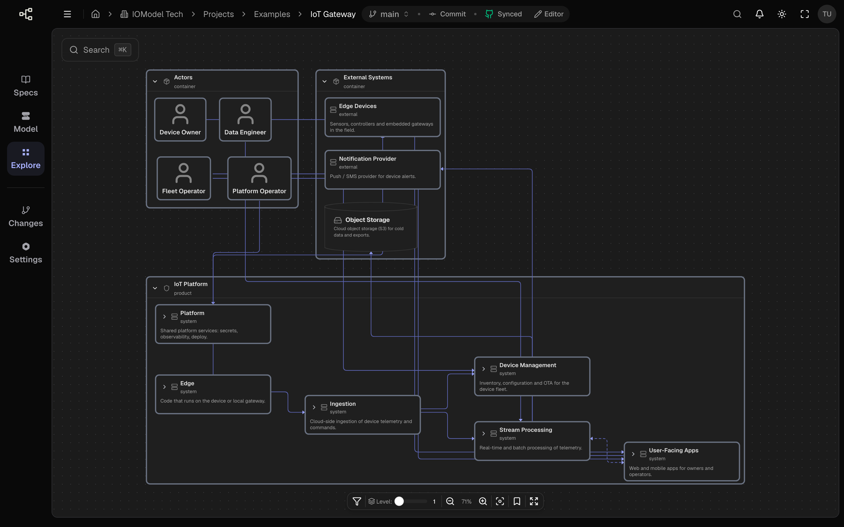
What it shows
- Objects from the model as nodes (vocabulary depends on the schema: e.g. systems and containers in C4, elements in ArchiMate, workloads in a deployment schema).
- Links between objects as directed edges.
- Nesting when the schema allows parent/child objects.
- Icons and figures derived from object type and schema rules.
Levels of detail
How deep you can drill depends on the schema and how you nest objects. With a C4-style schema, for example:
| Depth | Typical view |
|---|---|
| Low | Top-level systems and their relationships |
| Medium | Containers within systems |
| High | Finer-grained objects inside containers |
Expand on demand
You do not need separate diagrams per level. Increase depth or expand a node to reveal its children in place.
Reading the diagram
Start at the top
Begin zoomed out to see the overall shape and key relationships.
Expand what matters
Open the objects relevant to your question instead of everything at once.
Follow the links
Edges show direction and, when provided, labels that describe the relationship.
Keep link labels short and verb-based (calls, reads from, publishes to).
Readable edges make the structure self-explanatory.
Last updated on